Personal projects / Materials & heat
Copper clamshell furnace and pyrometer
A water-cooled copper furnace with an optical temperature-measurement system and a series of filament trials.
Open the numbered review →Chamber, viewing window, and pyrometer
Photos 44–52
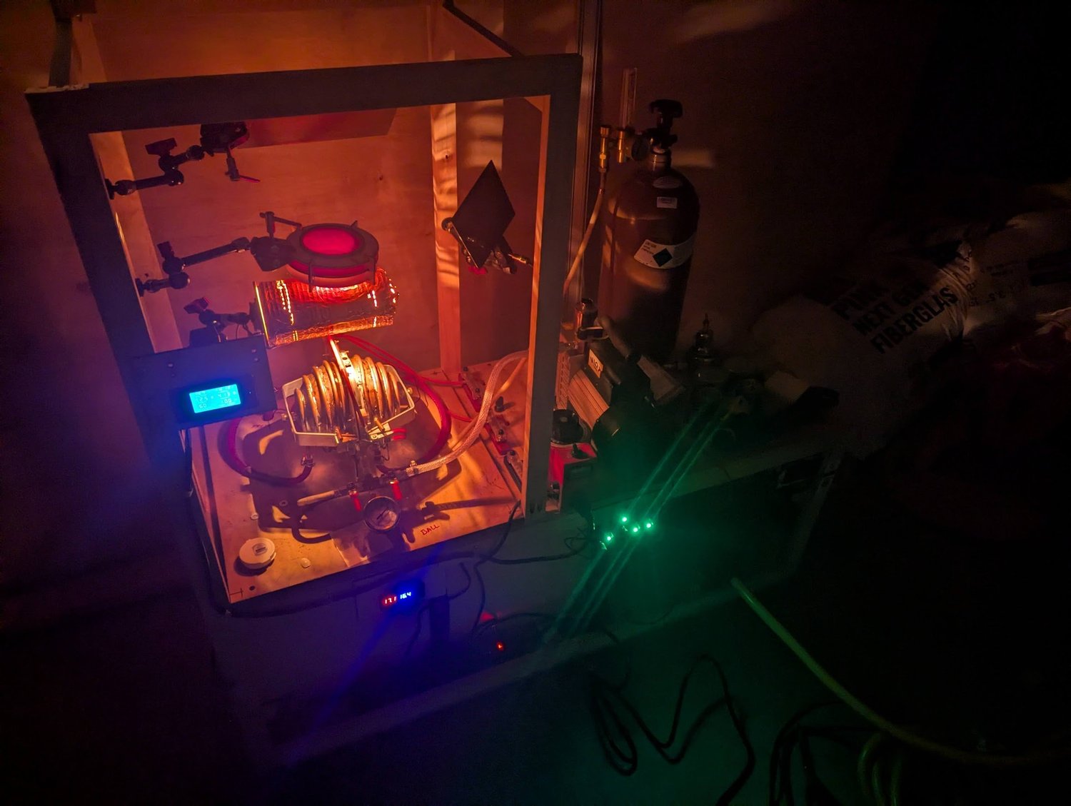
Two copper hemispheres form a hinged furnace chamber, with spiraling copper tubes carrying cooling water around each half. Electrical connections pass through the aluminum flange between them. Machining that large flange pushed the capacity of my milling machine. Above the chamber, the pyrometer’s glowing reference filament lights up the assembly.
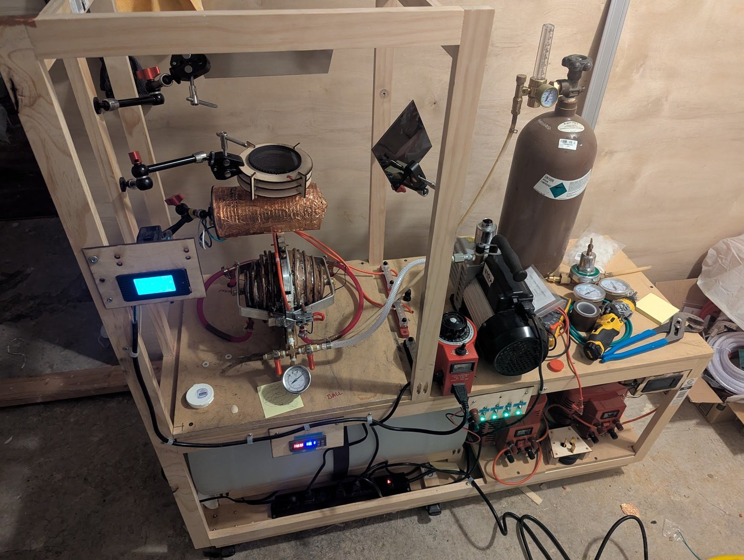
The same clamshell furnace with the room lights on. This wider view brings together the copper chamber, pyrometer, power equipment, and water-cooling system. It shows how the heating, measurement, and cooling parts of the experiment were arranged around one another.
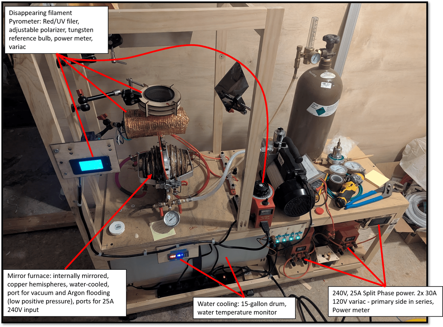
An annotated overview identifying the furnace, optical pyrometer, electrical controls, and water-cooling equipment. The labels explain how the chamber and its supporting systems fit together, including the reference lamp and filters used to observe the heated material.
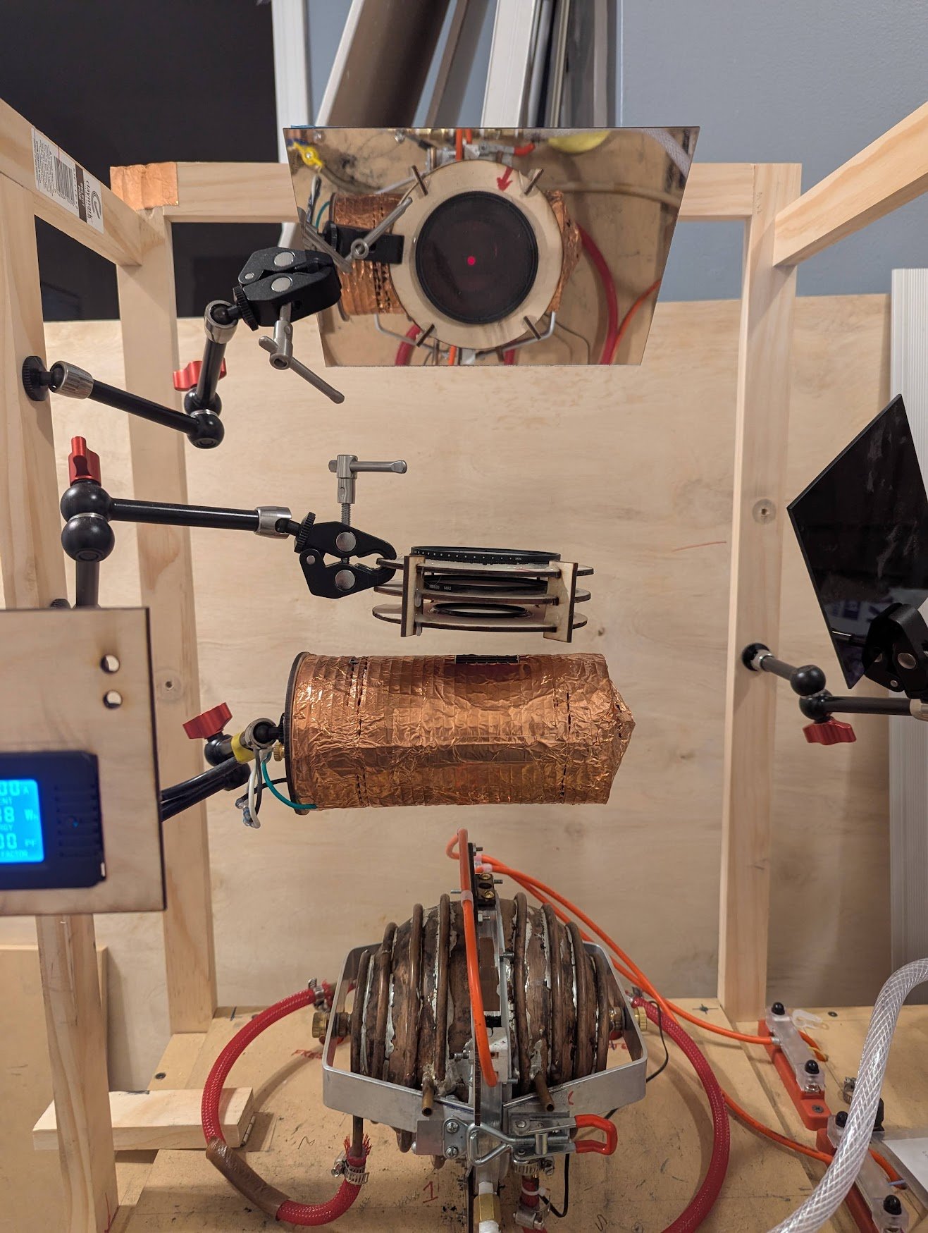
The pyrometer looks through a small opening in the furnace’s central flange. A reference filament appears in front of the hot target, and its brightness is adjusted until it blends into the target’s glow through a red filter. With calibration and an allowance for how strongly the target emits light, the reference setting can be used to estimate temperature. I built this setup to observe heated tungsten.
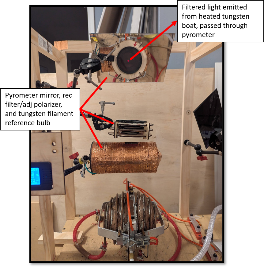
This annotated view identifies the tungsten reference lamp, red filter, adjustable polarizer, and viewing mirror. The filter selects red light for the brightness comparison, while the polarizer adjusts the transmitted brightness. A first-surface mirror redirects the view to the side, allowing observation without standing directly over the furnace.
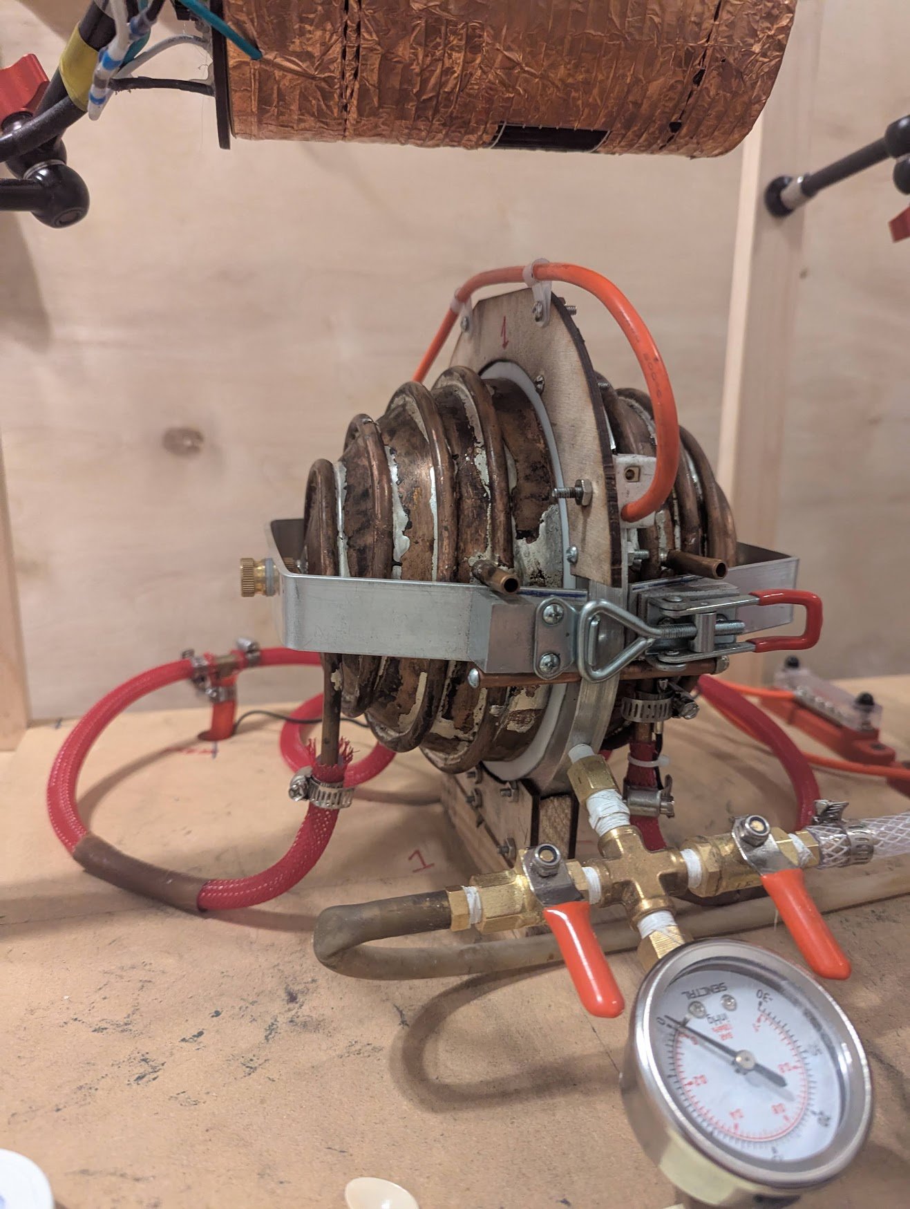
The copper furnace halves, cooling pipes, and aluminum clamping structure. The chamber connections used threaded plumbing fittings with PTFE (Teflon) thread-seal tape, red-handled ball valves, and a mechanical gauge indicating vacuum relative to atmospheric pressure. This was convenient hardware for an early experiment, but the plumbing valves and connections were not designed for vacuum service—a limitation I addressed in later designs.
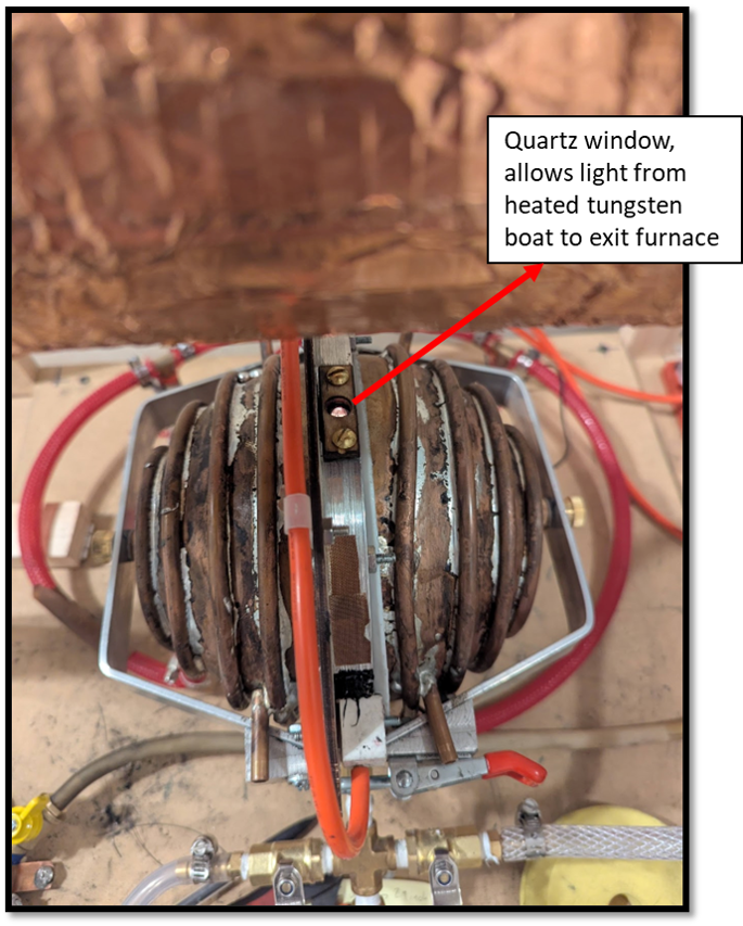
A small quartz window installed in an opening through the top of the aluminum flange. It provided an optical path out of the furnace so the pyrometer could observe the heated material inside while the chamber remained closed.
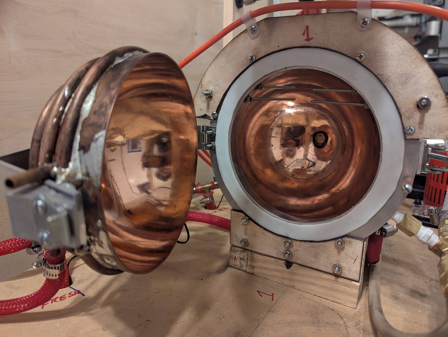
The polished copper interior was intended to reflect light back toward the sample. Four tungsten rods passed through the flange: two to suspend the crucible and two to connect the heating filament. Ceramic pieces positioned the rods, while silicone sealed the penetrations. These early trials exposed practical problems with fragile filaments, repeatable attachments, and keeping seals away from excessive heat, which shaped later feedthrough designs.
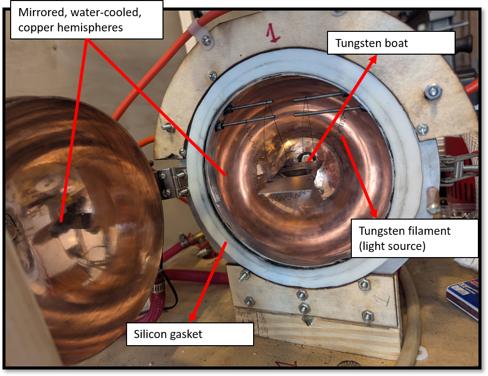
An annotated view of the tungsten boat—the small tray holding the sample—suspended on tungsten wires beside the heating filament. Gaskets sealed the chamber, and the vacuum was intended to reduce heat transfer through the surrounding gas. I also used argon to displace air. Balancing heat loss, oxygen control, and filament life became a central challenge of this furnace.
Filament tests and development
Photos 53–60
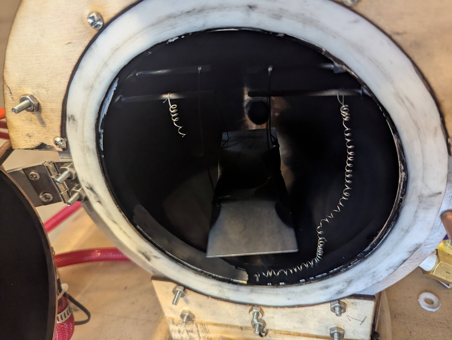
A broken filament and heavy dark deposits after a heating trial. The copper walls had started out polished and reflective. I came to see residual oxygen attacking the thin filament as a major problem, alongside the filament’s fragility and the difficulty of making durable electrical connections.
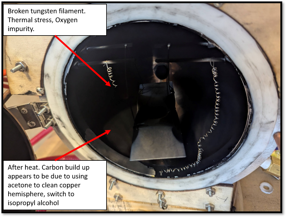
My original annotations record an early suspicion that cleaning-solvent residue might be responsible for the black coating. That was a working hypothesis: I did not establish the deposit’s composition or confirm that the solvent caused it. The image also documents a broken tungsten filament from the same series of tests.
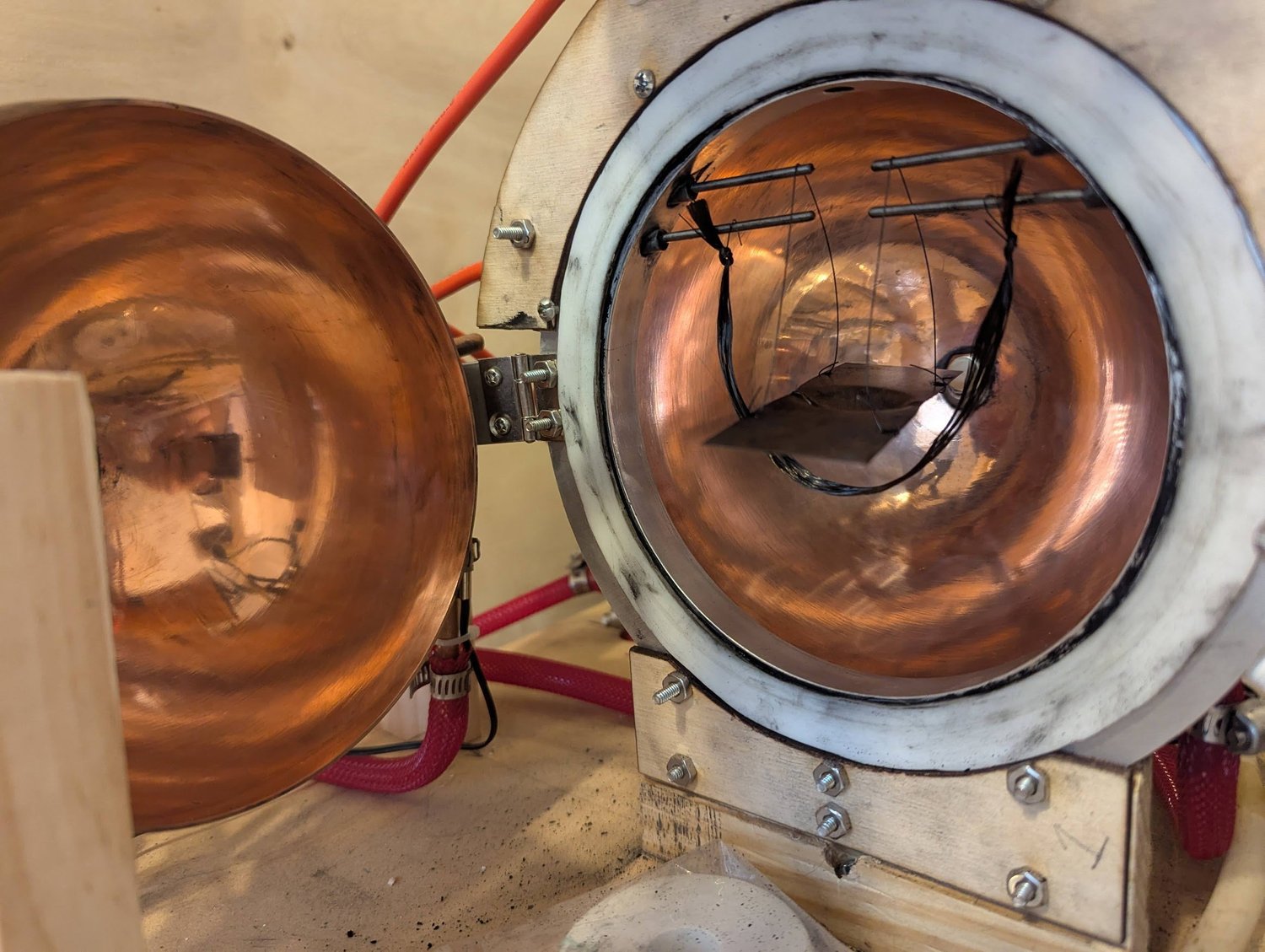
A trial using conductive carbon or graphite material as the heater. I no longer recall the exact material, but it failed quickly. The simple attachment around the feedthrough rods also highlighted the need for a more durable and repeatable way to connect the heating element.
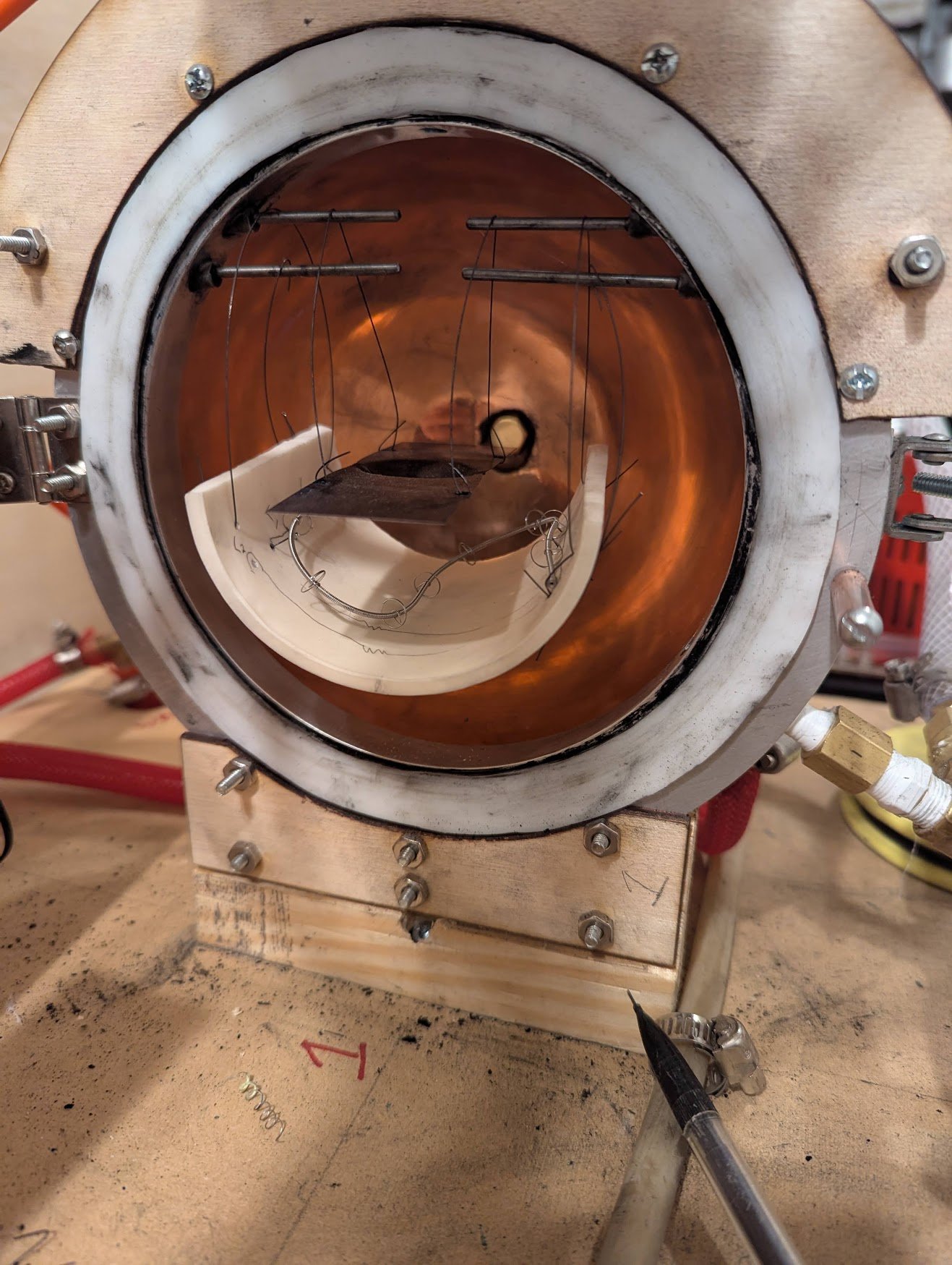
A delicate tungsten filament recovered from a halogen lamp, supported in a magnesium-oxide half-cylinder. The ceramic cradle was intended to support the filament mechanically while it served as the furnace’s heat source.
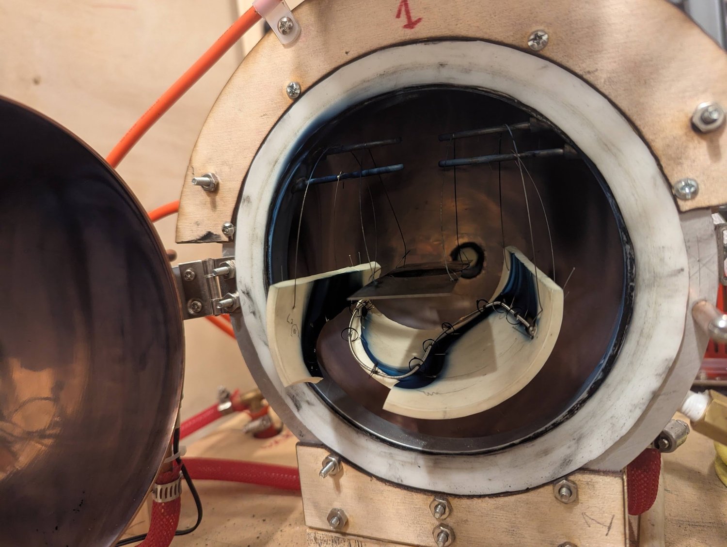
The magnesium-oxide support cracked, and the filament failed during this trial. Blue deposits appeared around the filament, which I interpreted as tungsten oxide. The result showed that both the support arrangement and the filament’s operating environment still needed improvement.
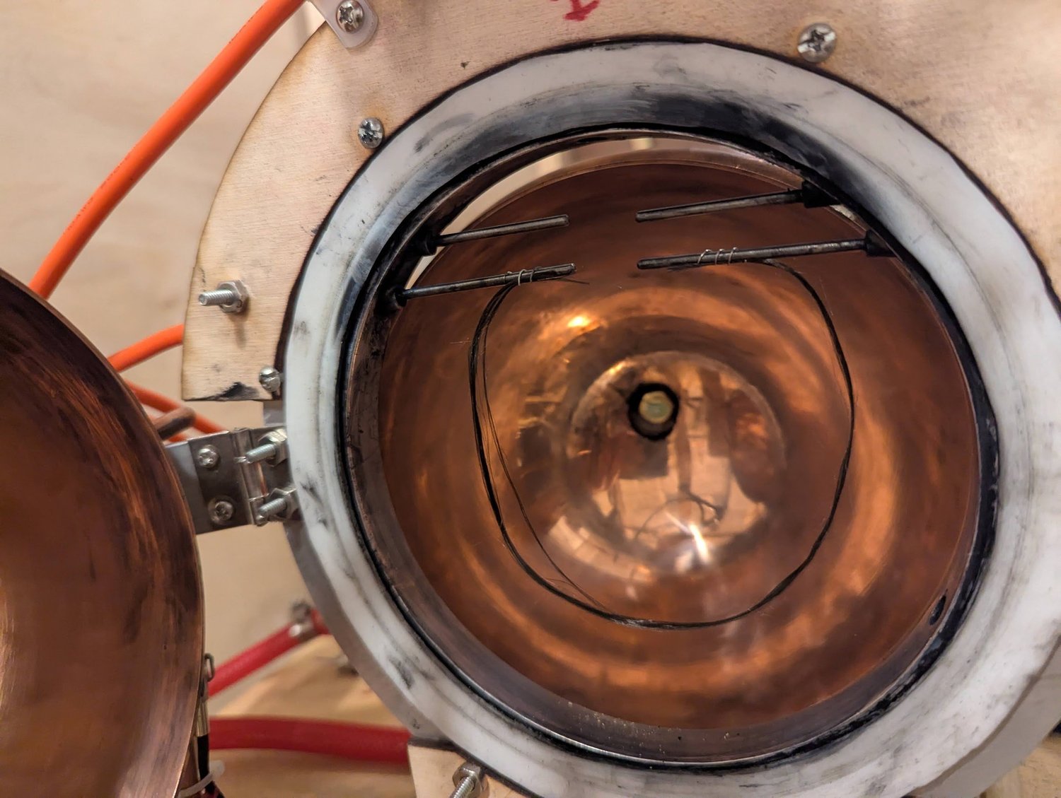
Another trial with a carbon-fiber or graphite-type heating material. This element also broke during testing. I was comparing several possible heater materials while trying to understand the recurring failures; I no longer recall the exact grade used here.
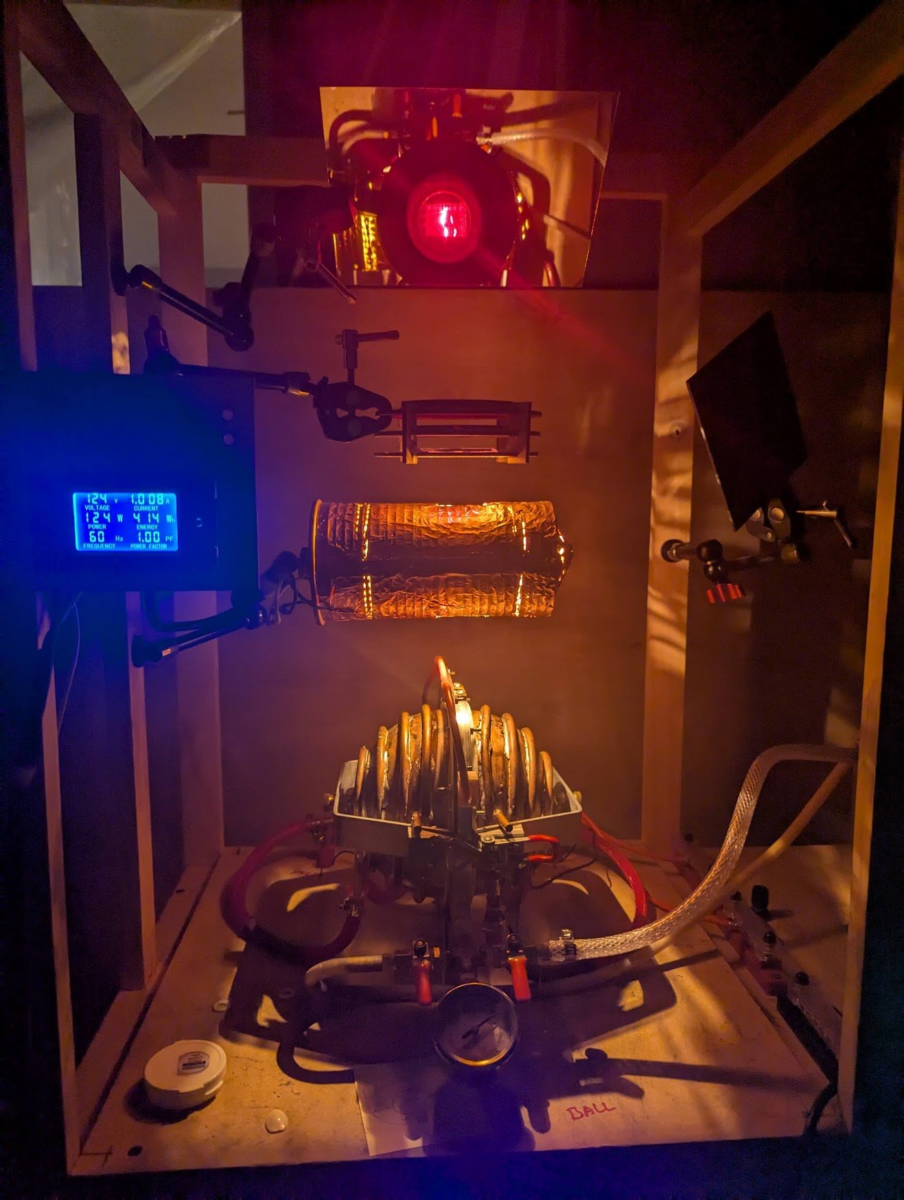
The illuminated meter on the left shows power supplied to the pyrometer’s 200-watt reference bulb. A Variac, outside this view, adjusted the lamp’s brightness. After matching the filament to the hot target, I used a separate lookup graph relating reference-lamp power to an estimated target temperature.
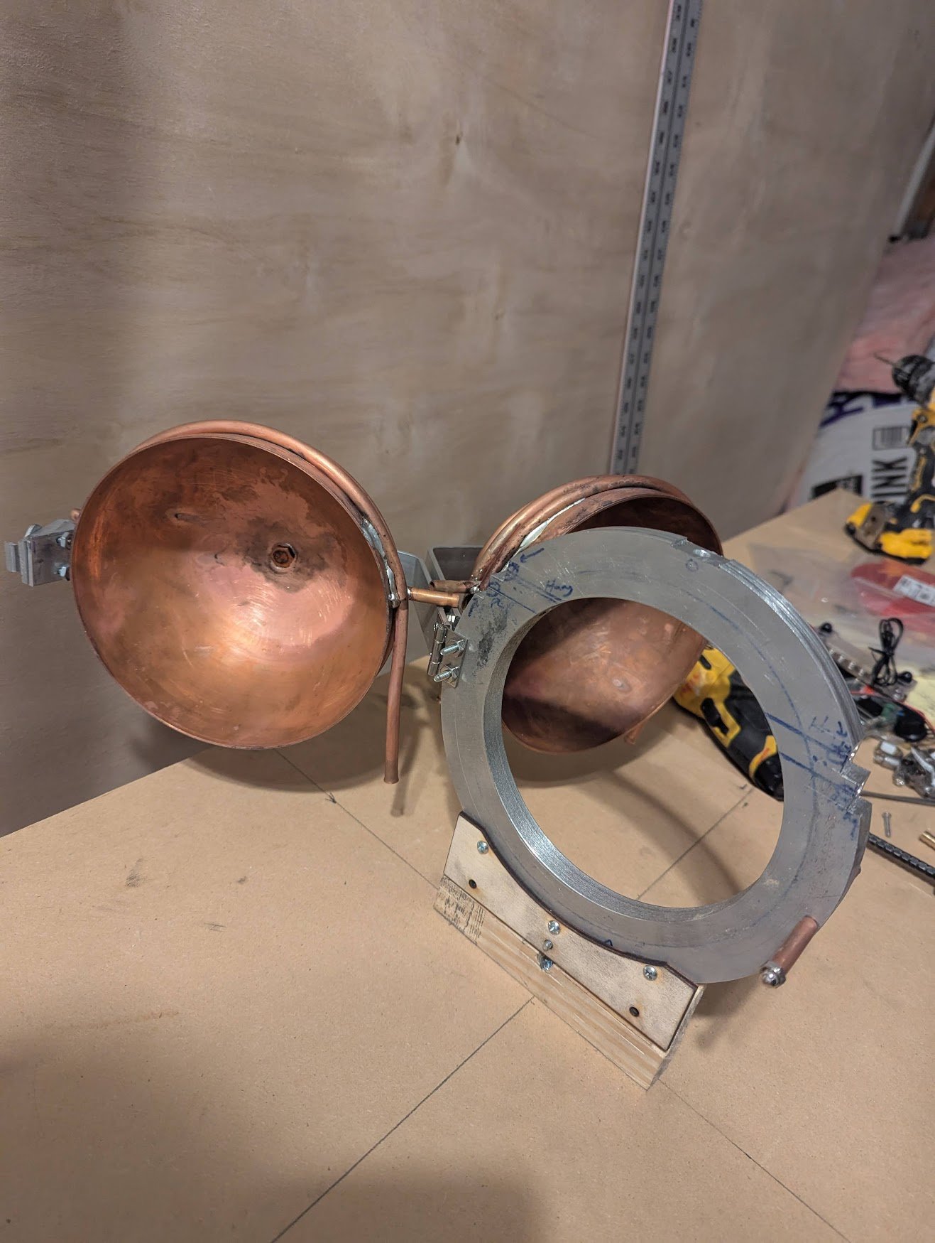
An early construction view of the clamshell furnace. The copper surfaces had not yet been polished, and several components were still missing. It shows the assembly before the reflective finish and the later heating and measurement experiments.