Personal projects / Sensors & electronics
Magnetic-launcher experiments
Magnetic-launcher prototypes and measurements, followed by earlier experiments and the original prototype.
Open the numbered review →Later prototype and measurements
Photos 86–88
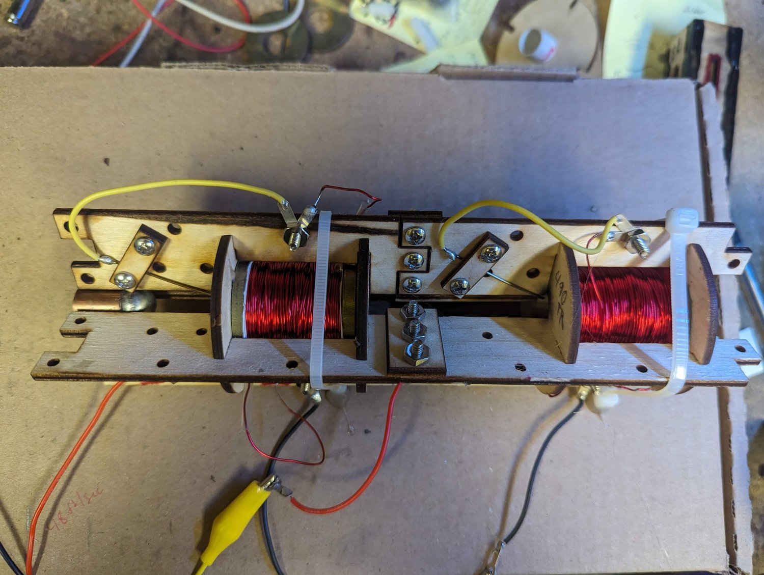
An experimental electromagnetic launcher from an earlier electronics project. I used it to explore the relationship between electromagnetism, electrical switching, and motion, and documented several prototype variations during the work.
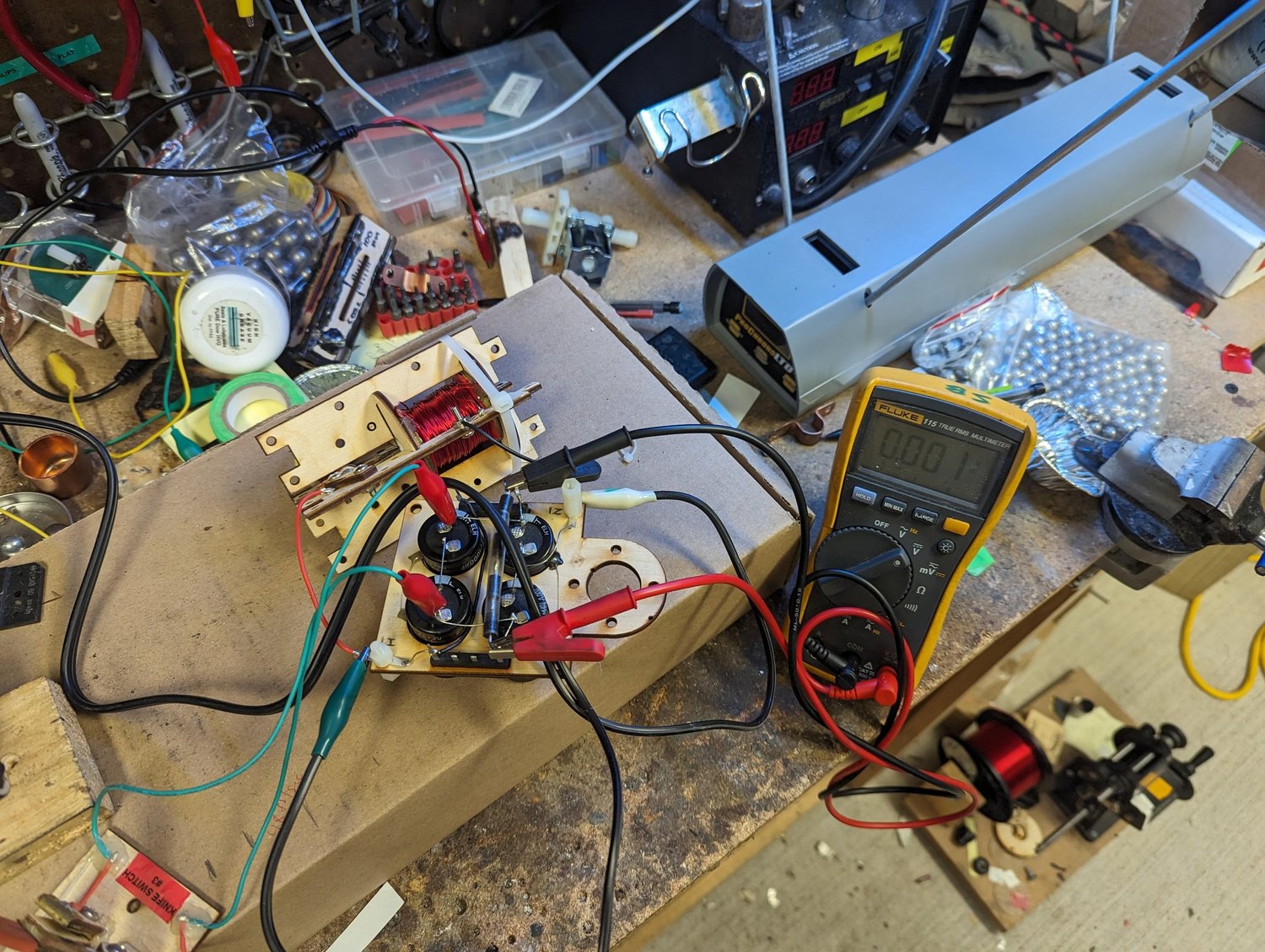
A single-stage prototype beside a chronograph, an instrument used to measure the speed of a passing object. I no longer recall the measured result reliably, so this photograph records the test arrangement without assigning a speed.
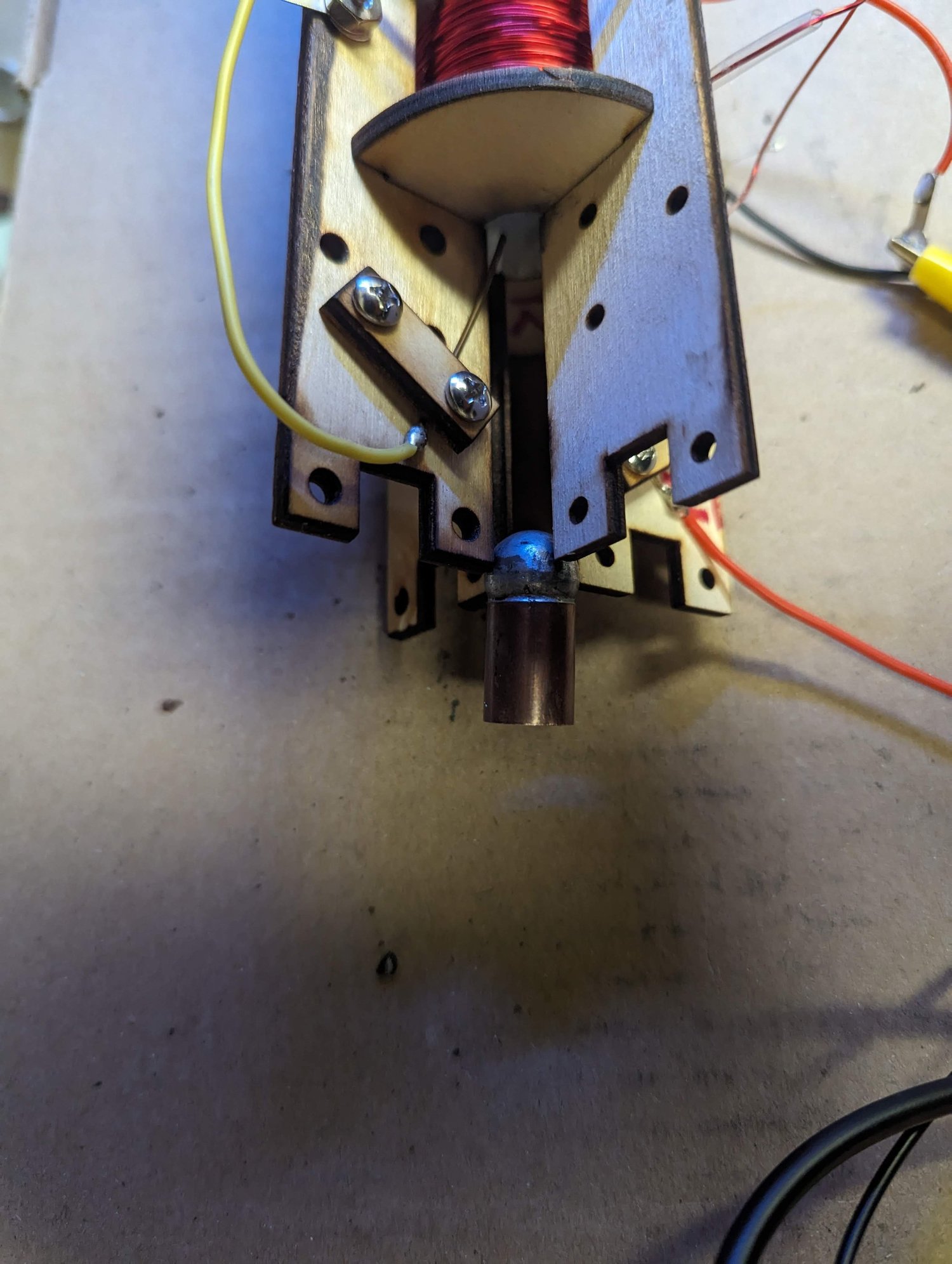
A closer view of one end of the electromagnetic launcher prototype. This image documents the physical assembly from another angle as part of the project record.
See it in motion
Prototype testing
Photos 93–96
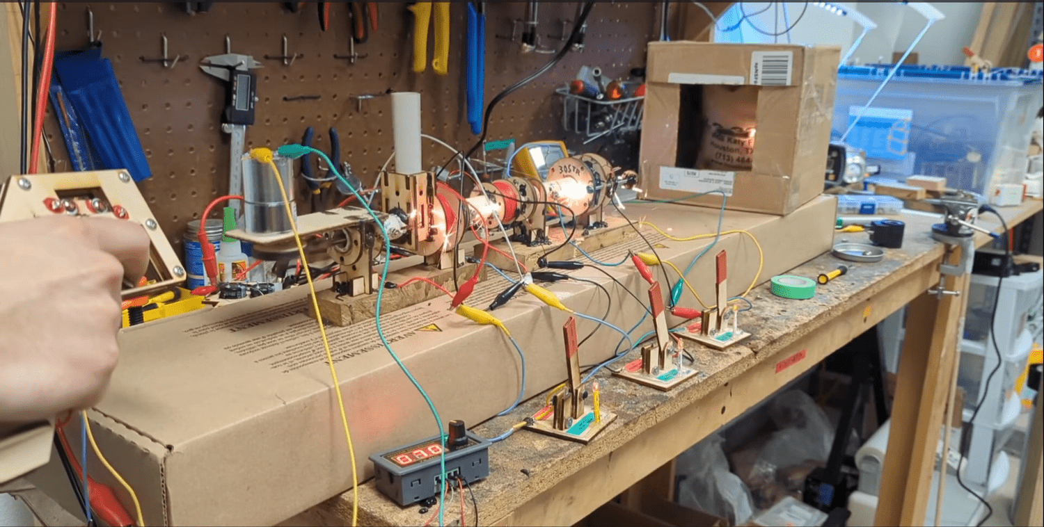
An earlier experimental electromagnetic launcher, shown as a complete assembly. This project brought together electrical switching, mechanical components, and motion measurement, with several prototype versions documented along the way.
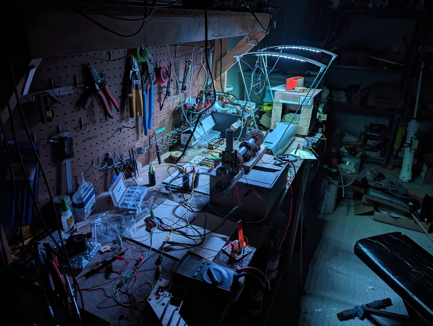
A chronograph measurement setup used during the prototype tests. A chronograph measures the speed of an object as it passes through its sensing area. This photograph records the measurement equipment used with the experiment.
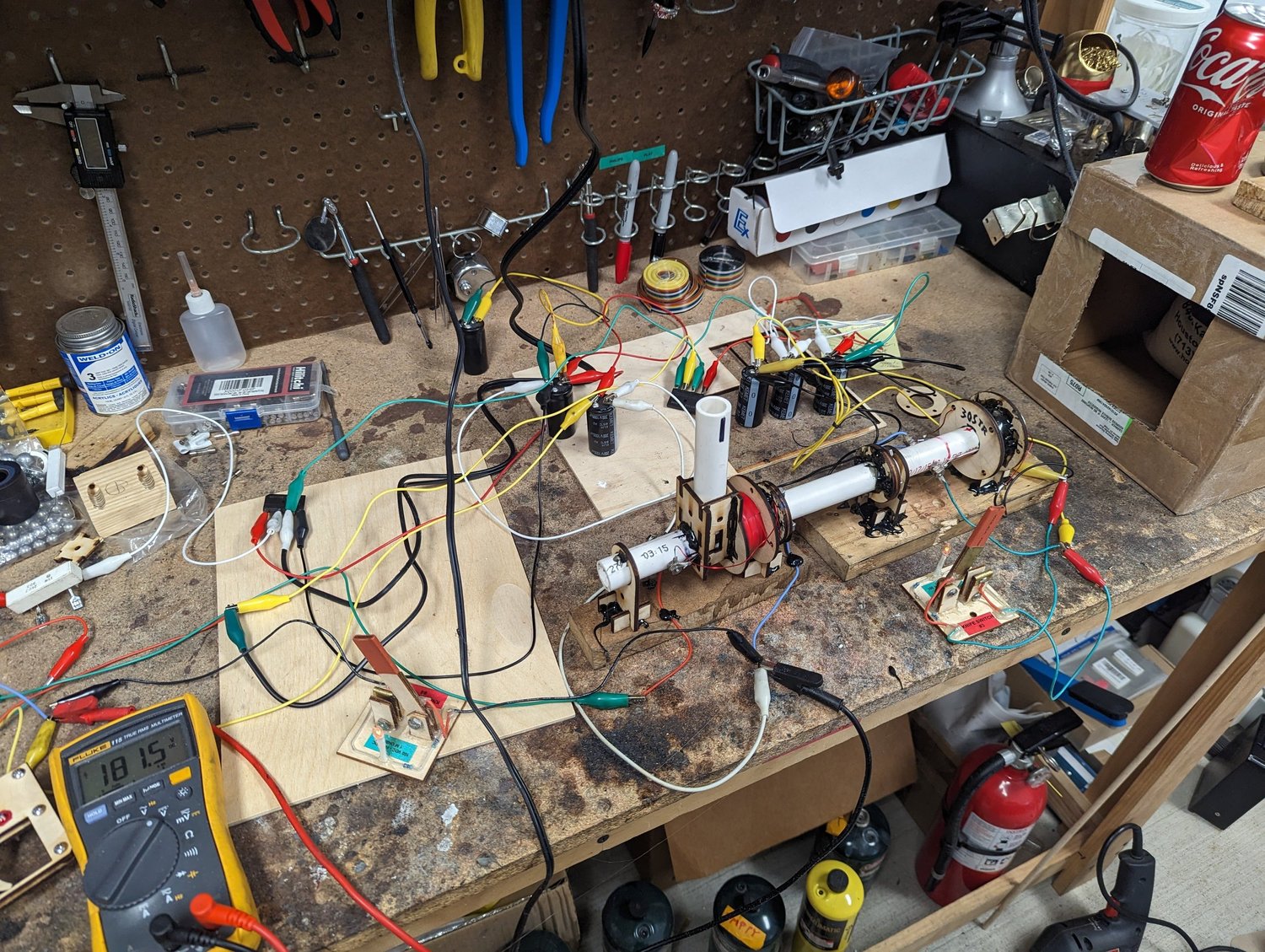
A view from the troubleshooting work on the electromagnetic-launcher prototype. I documented the individual assemblies while investigating problems that came up during testing.
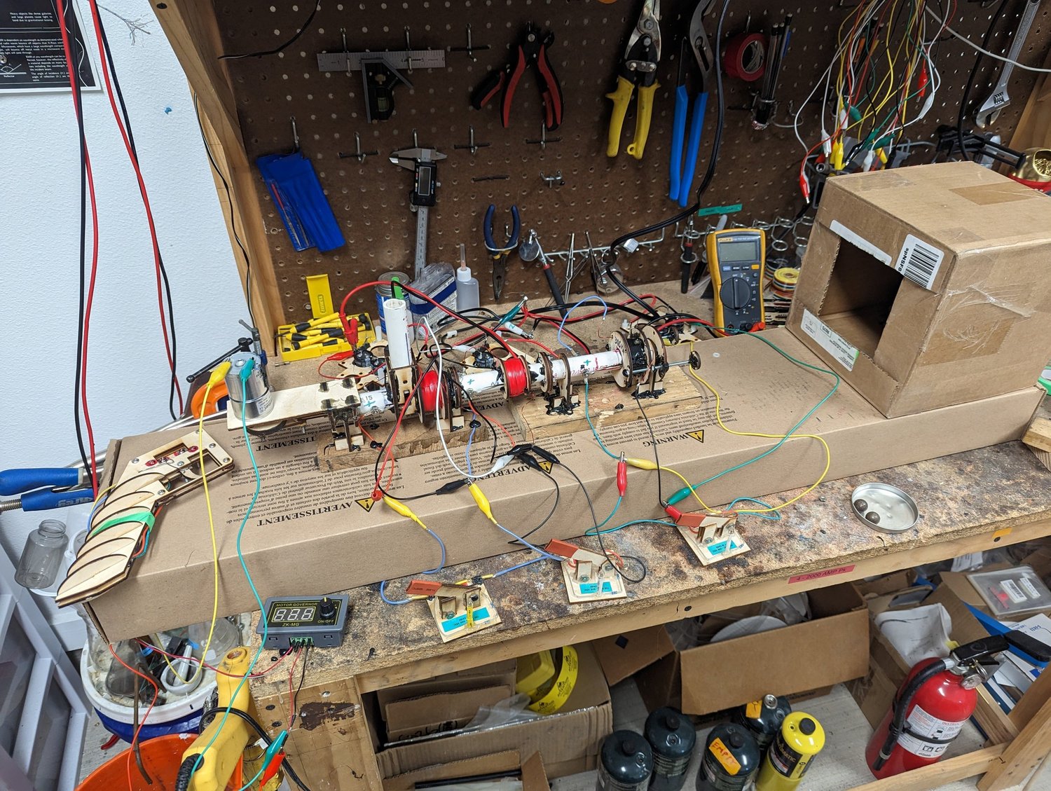
Another photograph from the same series of prototype inspections and tests. Together, these images record the experimental assembly and the work involved in evaluating it.
See it in motion
Electroplating experiments
Photos 89–92
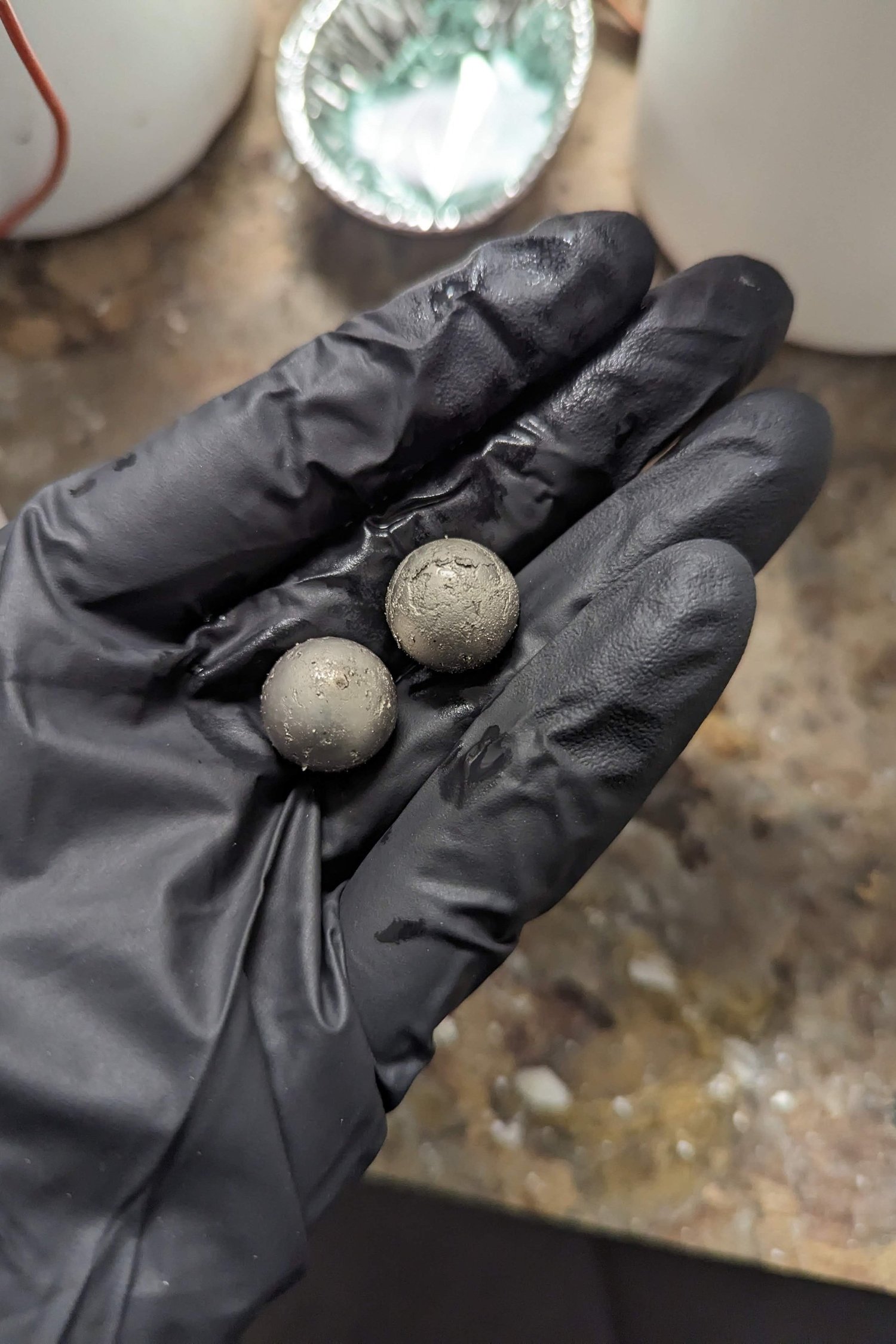
Surface-finishing experiments on iron ball bearings using nickel and copper coatings. This group of photographs records the plating work and the handling of the small metal samples during an earlier electronics project.
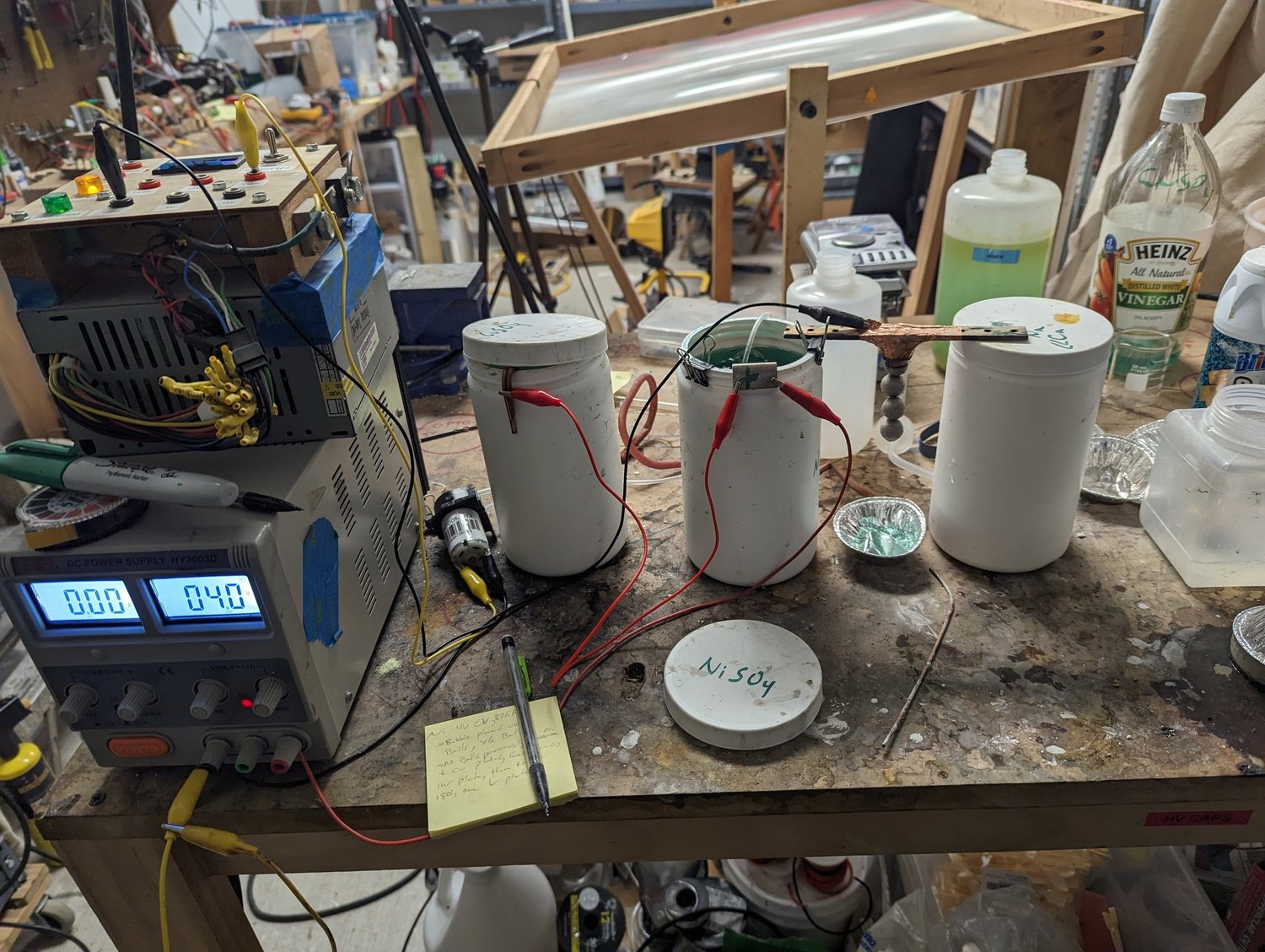
The bench setup for the coating trials, including a power supply, separate plating containers, and air-bubbling equipment. I used this arrangement while experimenting with metal finishes on the ball-bearing samples.
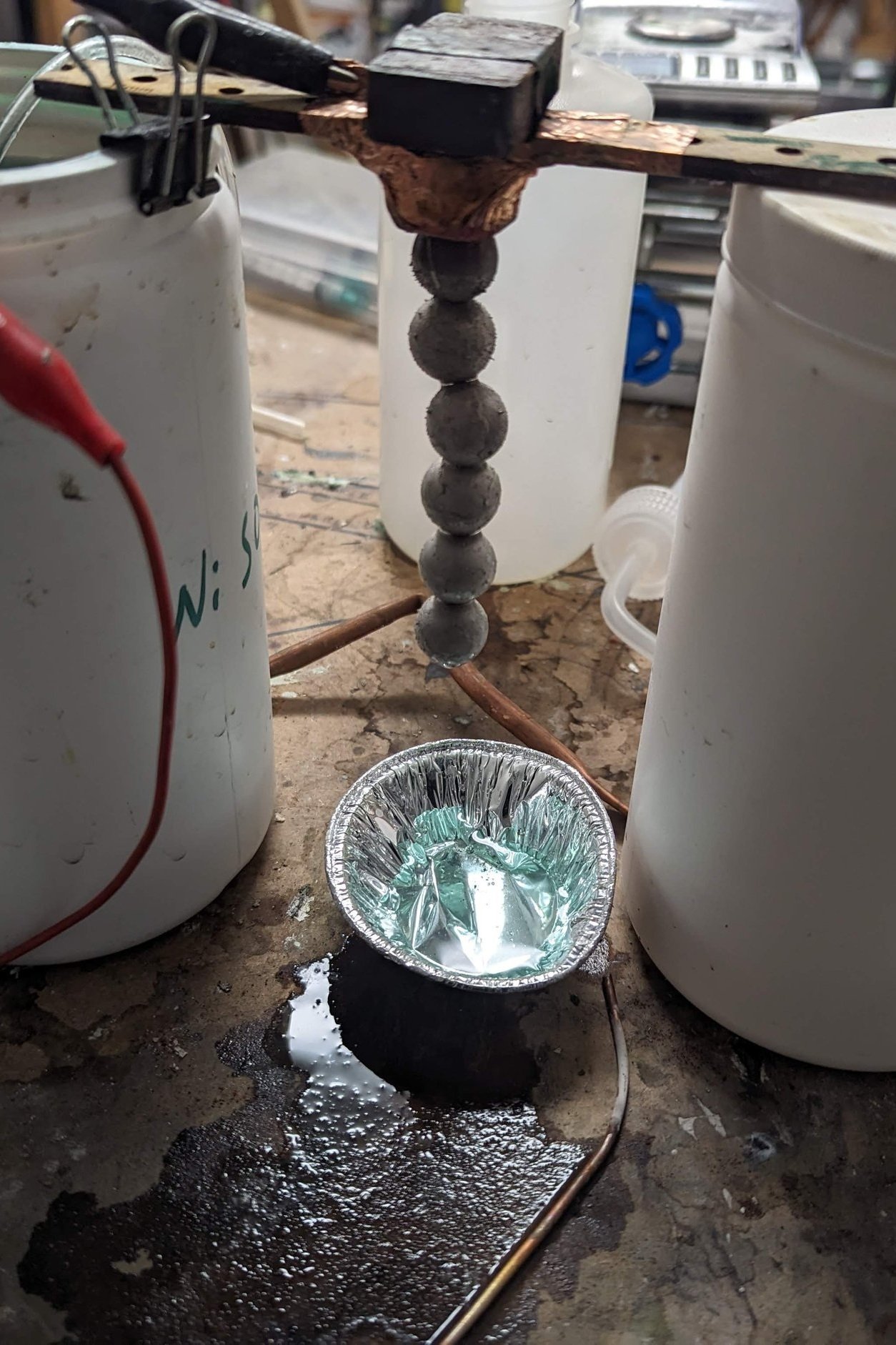
The ball-bearing samples being rinsed during the plating work. This photograph documents the handling and cleaning of the small parts between treatments.
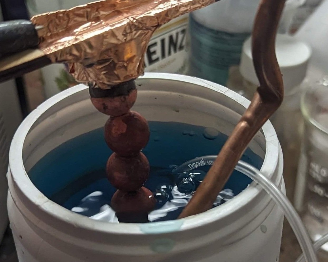
The metal samples immersed in one of the plating containers. This image is part of the record of my nickel and copper surface-finishing experiments.
Earlier prototype development
Photos 350, 357–358
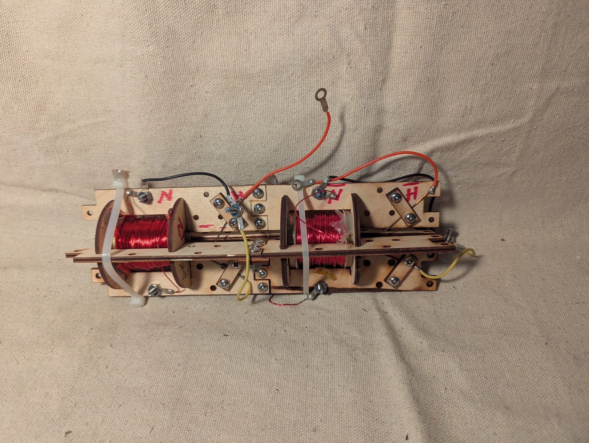
A later layout of the early coilgun experiment, with two experimental stages mounted together. This photograph records the development of the prototype's mechanical arrangement.
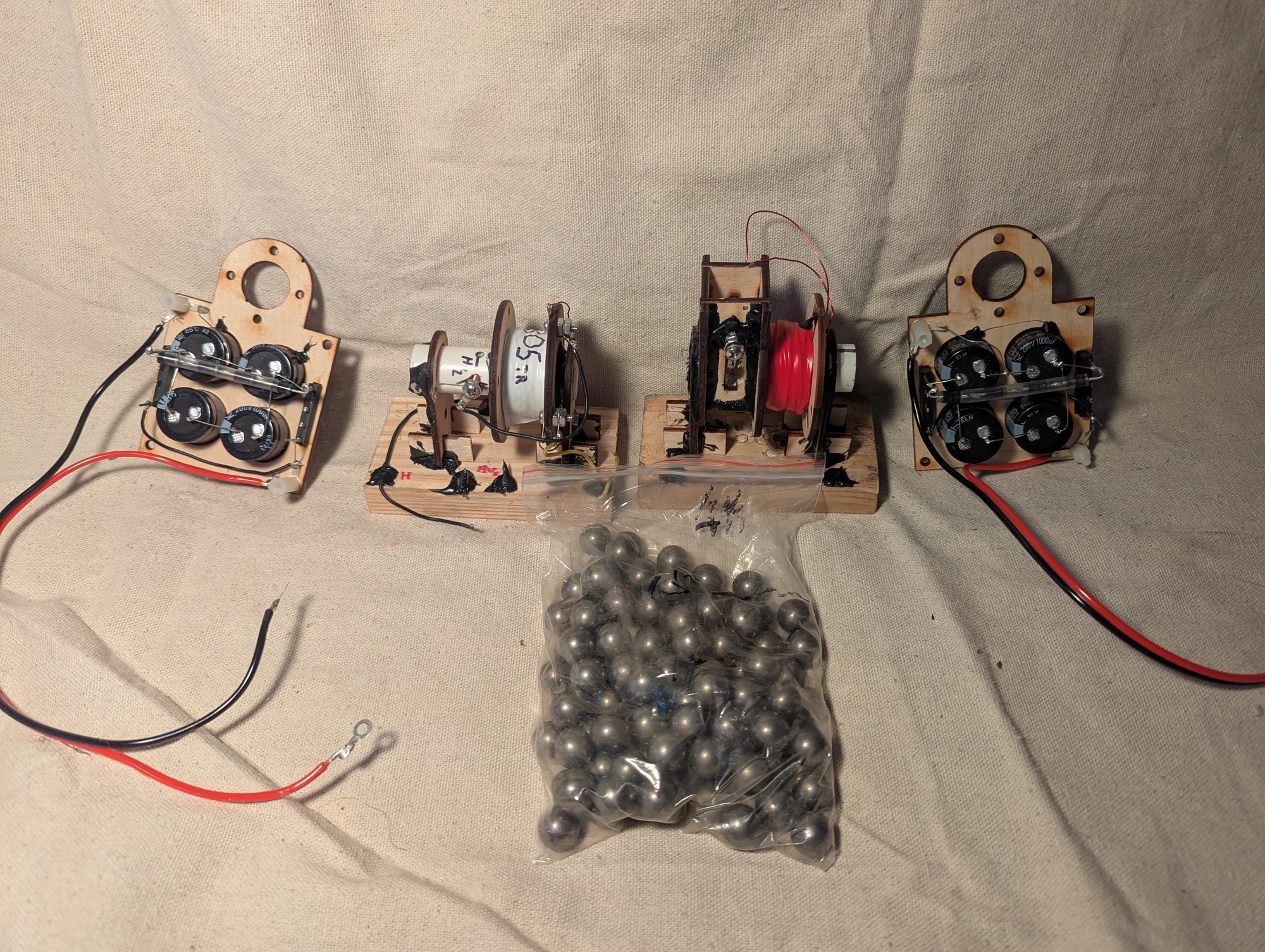
A bench layout from an early coilgun experiment, shown with its test hardware and steel balls. I was exploring mechanical triggering as part of the prototype.
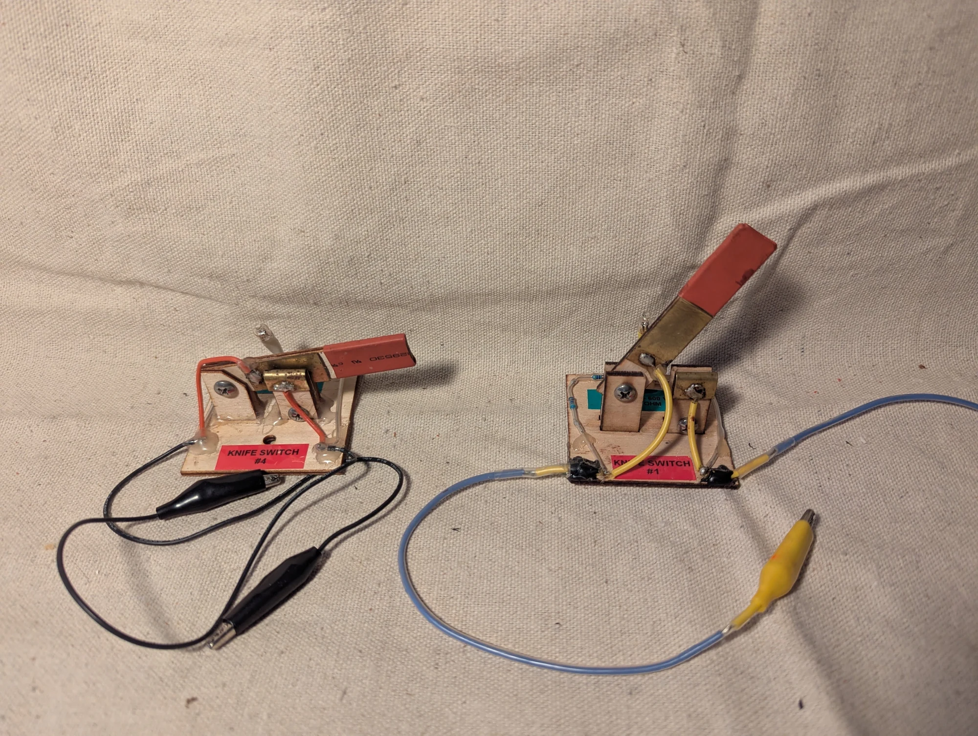
Two knife switches used in my early electrical and coilgun experiments, with brass contacts and small neon indicators. The indicators were intended to show whether a voltage difference was present across the contacts.
Earlier prototype
Photos 267, 271, 274
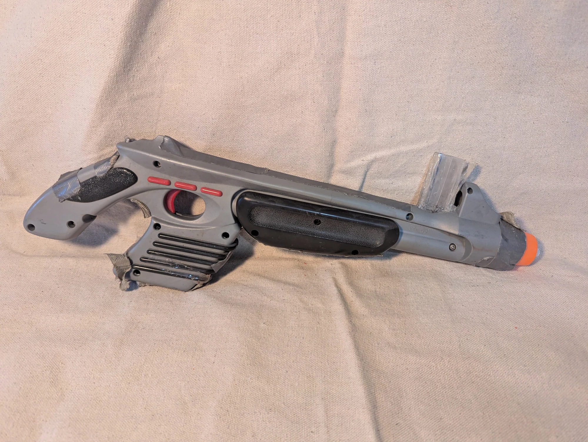
An early coilgun modification I made during middle or high school, incorporating a camera-flash charging circuit. This is the school-years prototype, which predates the later magnetic-launcher designs shown in this project. I do not recall the exact year.
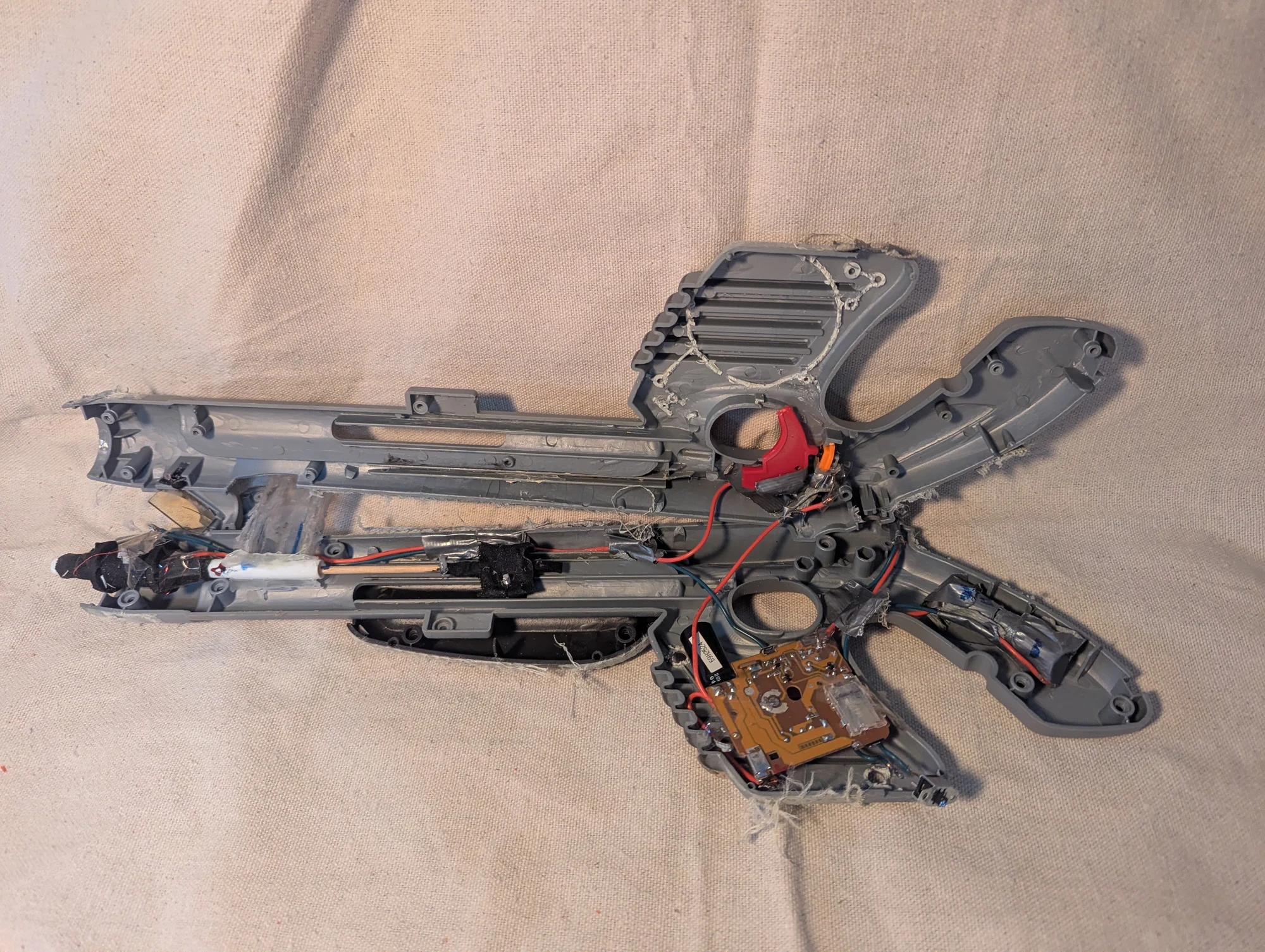
An interior view of the coilgun modification I made during middle or high school, showing its circuit hardware and wiring. This belongs to the early school-years prototype rather than the later versions.
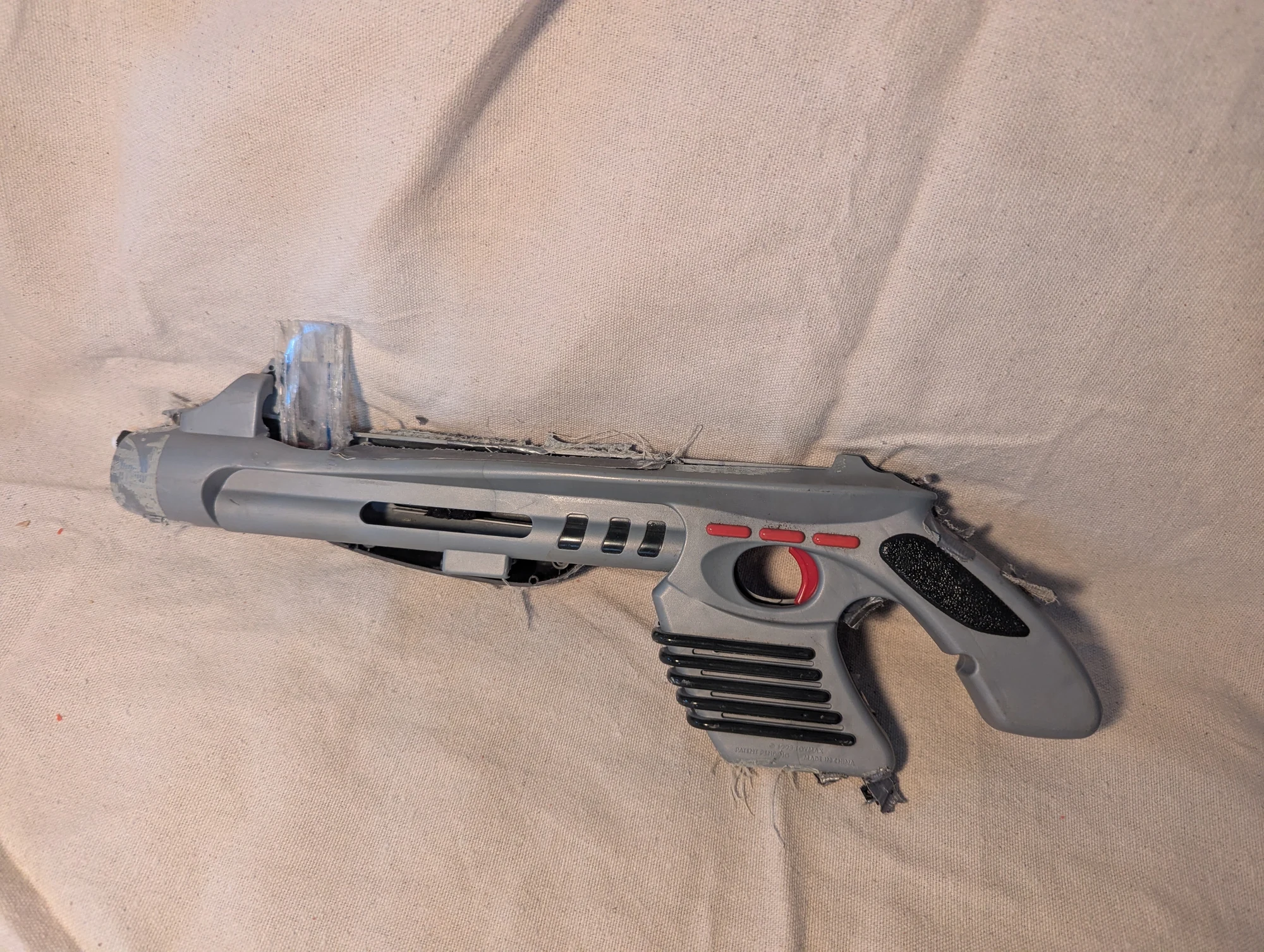
Another exterior view of the coilgun modification I made during middle or high school. This is the same early prototype shown in Photos 267–272; the later designs are shown separately in this project.